Lab4 - Motors and Open Loop Control
Published:
Objective
The purpose of this lab is to change from manual to open loop control of the car. The car should be able to execute a pre-programmed series of moves, using the Artemis board and two dual motor drivers.
Keywords
Lower limit PWM value, Motot Spinning Calibration, Open-Loop Control
Prelab
The following diagram shows my intended connections between motor drivers, Artemis, and battery. Artemis pin assignments: pin 4 for BIN1 & AIN1, pin A5 for BIN2 & AIN2, pin A15 for BIN2 & AIN2, pin A16 for BIN1 & AIN1. (pin 4 & A5 control one motor and A15 & A16 control the other one.)

We have two batteries, and I decided to use one of them to power the Artemis board and the other one to power the motors. First reason is that separate power supply is better considering motors consume much more power. Second reason is that the current from motors would change drastically when doing some motions. The unstable current may damage the Artemis circuit, to lower down the transient noise effect.
Lab Tasks
Task 1 - Setup with power supply and oscilloscope hookup
To test the dual motor driver, I used a power supply to provide a controllable voltage limit at 3.7V (through Channel3), and the output of the driver was read using an oscilloscope:


Task 2 - Power supply setting
The output voltage curve is shown as a square wave, which validates the motor driver. Also, from the oscilloscope, the peak-to-peak voltage is 4.64V which should be caused by the noise from the motor driver. To simulate the real battery charging the robot, the voltage from the power supply was set to the same voltage output as the 850mAh battery – 3.7V.
Task 3 - AnalogWrite code to tests the motor drivers
I used a sketch file to test the motor drivers by setting the output pins and the PWM values.

Task 4 - Image of your oscilloscope
After uploading the code to Artemis, I used the oscilloscope to measure the input and output of the motor driver. (Note. Before I assembled all components, I forgot to take pictures or other ways to record the performance of my motor driver. So, I used the USB from laptop to power Artemis instead to test. In the following parts, everything went well and there was no bugs of motor drivers’ input and output)
The probes connection is shown as:

The oscilloscope image is :

I used the Channel 1 to test pin BIN2 & AIN2 and used Channel 2 to test pin BOUT2 & AOUT2. The Channel 2 curve shows the inverted Channel 1 curve with some delay, which indicates the motor driver works well. The same test was applied to another motor driver which got similar results.
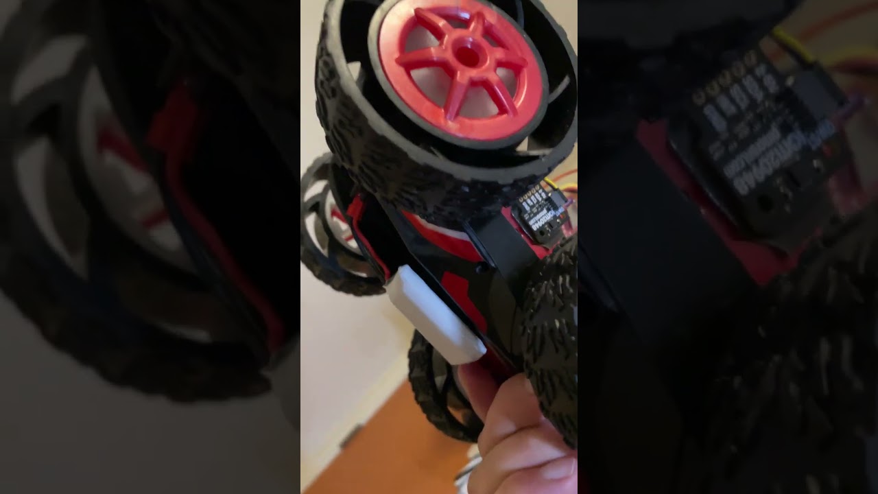
Task 5 - One side of Wheels spinning
The one side of wheels spinning video is:

Task 6 - Both wheels spinning with battery driving the motor drivers
I assembled the sensors, Artemis and batteries and test the two wheels spinning with the following code:

The video is:
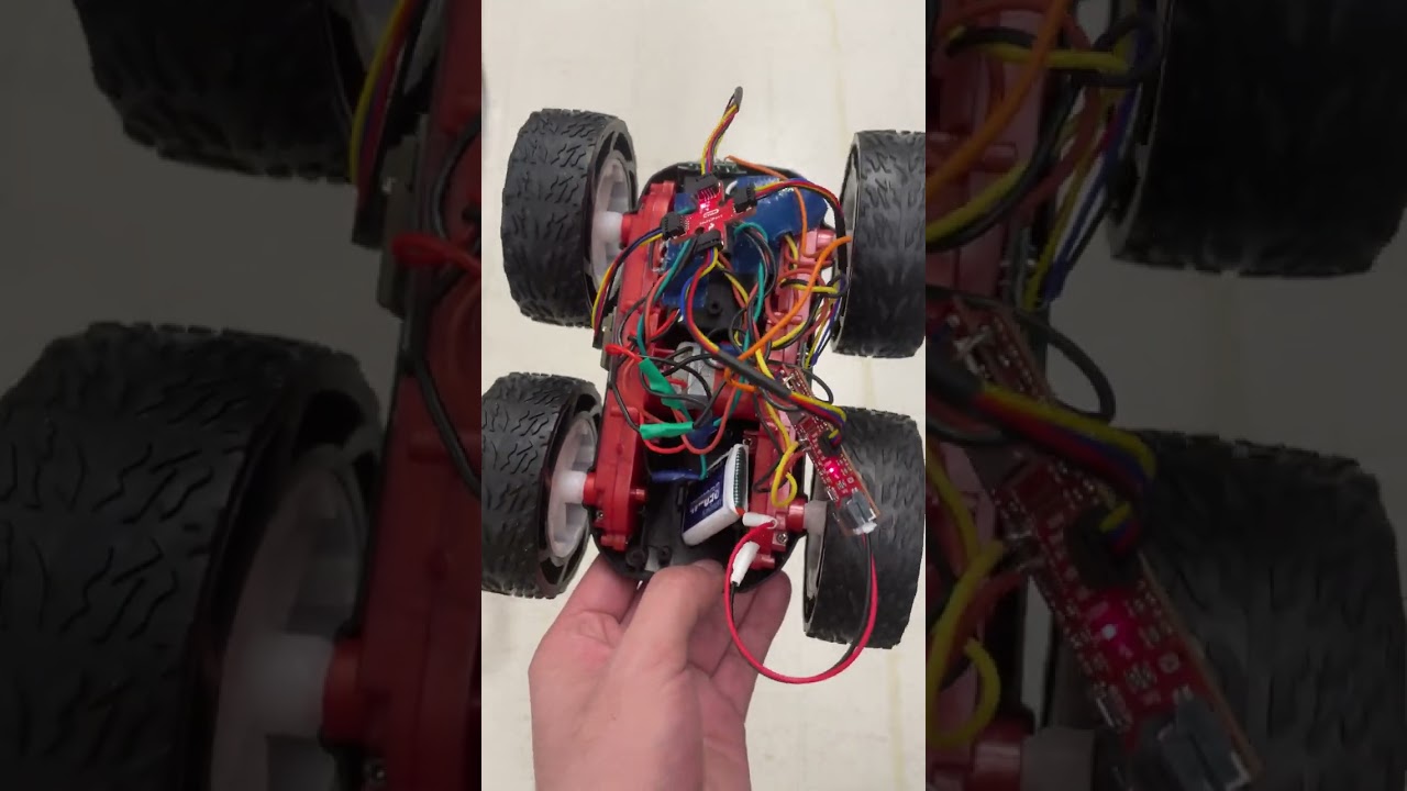
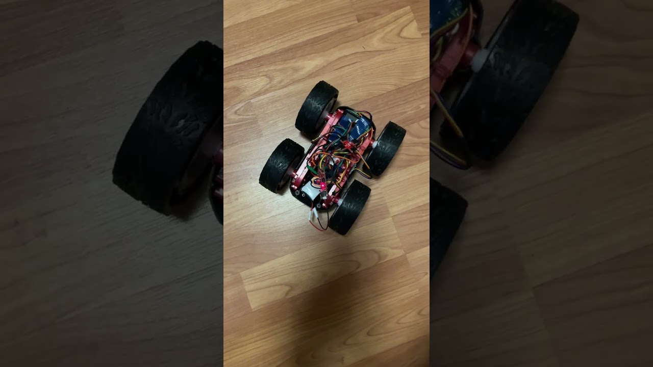
Task 7 - Picture of all the components secured in the car
Here is the picture of the car:

Task 8 - Lower limit PWM value discussion
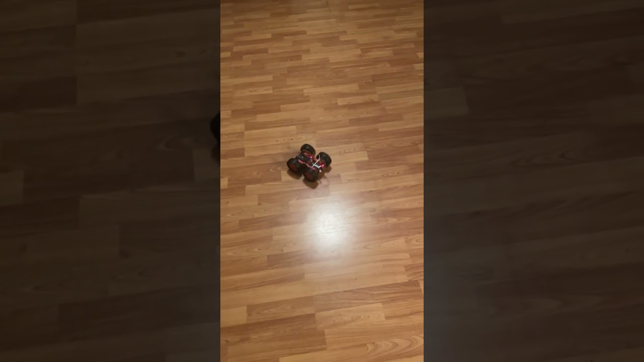
To understand motors’ range, I tested the lower limit value of the robot, by changing the PWM value until the robot was able to start moving from a stationary position on the ground. This process needed many trials. The testing code is like:

And the video which shows the robot just merely could move forward:
As for the lower limit of on-axis turns, this needed the two sides of wheels rotate in opposite directions and needed much larger PWM power to do so. After trials, the code is shown as follows:

And the video which shows the robot just could make the on-axis turns:
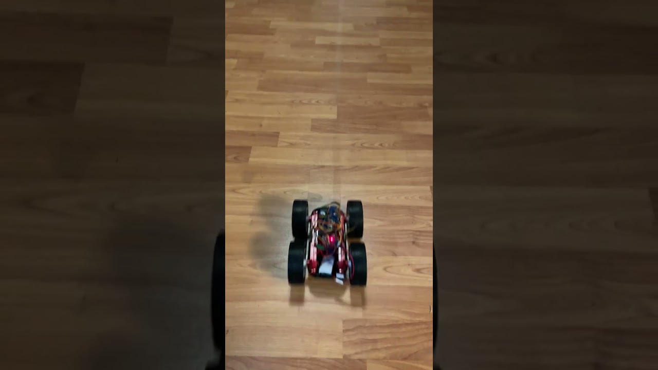
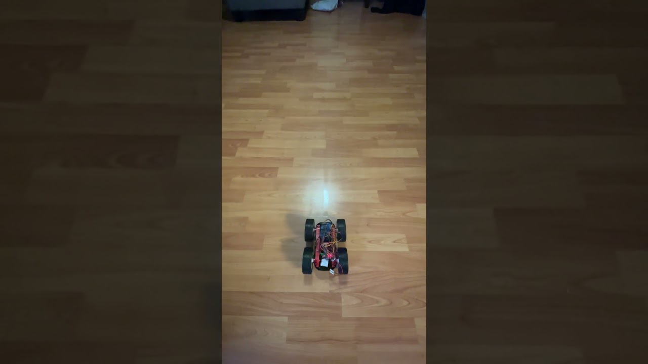
Task 9 - Motor spinning Calibration
When I set the same PWM duty cycle values to the two motors, I found that the right side rotates faster and the robot car’s trajectory always bended to the left side. So, I applied the calibration factor to let the robot car go straight lines. (Note. I tested and did the experiments at home on the wooden floor)
Generally I applied the idea from Bisection Method – First, test certain value, and see whether it is larger or smaller. If larger, then apply a smaller one. If smaller, then apply a larger one. Go on the iterations until find out the appropriate value that can let the robot car go straight line.
I tested the robot by optimizing the parameter cali_factor and use the fd_general_power as the basic power.

I first tested the general PWM value as 150 for the left side, and the calibration factor is about 0.71.
Then I tested the PWM value as 200 for the left side, and the calibration factor is about 0.805.
Then I discovered that the calibration factors are not linear with the PWM values. I generated the rough function curve for left_PWM_value & right_PWM_value as follows:


Task 10 - Open loop control demonstration
To demonstrate the open loop control, I implemented a new command which contains robot moving forward for 1 second, rotating for certain degrees, and moving forward for another 1 second. I sent this command through BLE communication.
The command open_loop_control is shown as follows:

And the video for the robot running this command is: