Lab6 - PID Orientation Control
Published:
Objective
The purpose of this lab is to realise orientation PID using the IMU. In Lab 5, PID control was done on wall distance using the ToF sensors, this lab will involve controlling the yaw of the robot using the IMU.
Keywords
BLE, PID Control, Orientation
Prelab - Optimization of BLE Data Transfer Module
As for this lab, the BLE module is quite similar to that of Lab5 - Linear PID Distance Control. I recorded the important debug readings inside the PID control loop. Then, I used another case SEND_PID_ORIENT_DEBUG_READINGS to continuously send the data back to the PC after the robot car finished the PID control mission.

On the PC, I used another notification handler function to receive, parse and store the data.

Lab Tasks
Task 1 - Range/Samping Discussion
Basically, what we get from the IMU is the angular velocity. So, in order to get the orientation angle in degrees, we need to “integrate” the velocity during dt to estimate the angle:

From the official document of the IMU, there is the angular rate’s modes:

This is very critical because when the robot car’s orientation angle suddenly changes, the angular velocity from the sudden change can be huge, which the IMU cannot accurately measure. During the physical experiments in the lab, I discovered that when I kicked the robot car to change its orientation hugely, because of the “low” sampling rate of the angular velocities, the IMU will tend to return a orientation angle which is rather lower than the actual angle. (Note This has been tested even when the rate was changed to the maximum 2000dps)
So, to reduce the error, I directly changed the angular rate from the default 250dps to the maximum 2000dps.
Task 2 - Range of P-Controller Gain
In this task, the error is from the orientation angle. The value of the angle in degrees from IMU can be some hundred even over ±360 degrees. But the IMU will tend to firstly get the initial orientation angle within [-360, 360] degrees. So, the error is about some hundred. In this case, the order of magnitude of the p-controller’s gain $K_p$ will be approximately between $10^{-1}$ to $10^0$.
Task 3 - P/I/D Controller Implementation
Similar to Lab5, I used the heuristic procedure (#1) to find the value of P/I/D:

Also, before I implemented the PID, I used the case PID_STATUS_INI to initialize all the PID-related parameters:

As for the limit of the PWM duty cycle value, I set the deadband to 180 for car’s rotatation and set the 255 as the maximum value.
I set the target orientation angle to be 180 degrees.
P-Controller
The general implementation method of P-controller is: $P = K_p \times \text{Error}$, where the error is: $\text{YawError}=\text{TargetYaw}-\text{CurrentYaw}$
The first step was to set $K_i$ and $K_d$ to 0, and increase the $K_p$ from 0.1 to 5. Then, I found that when $K_p$ is 2, the performance is stable and quite good.
The angle error vs time:

The P value vs time:

The video for Kp=2 is shown as:
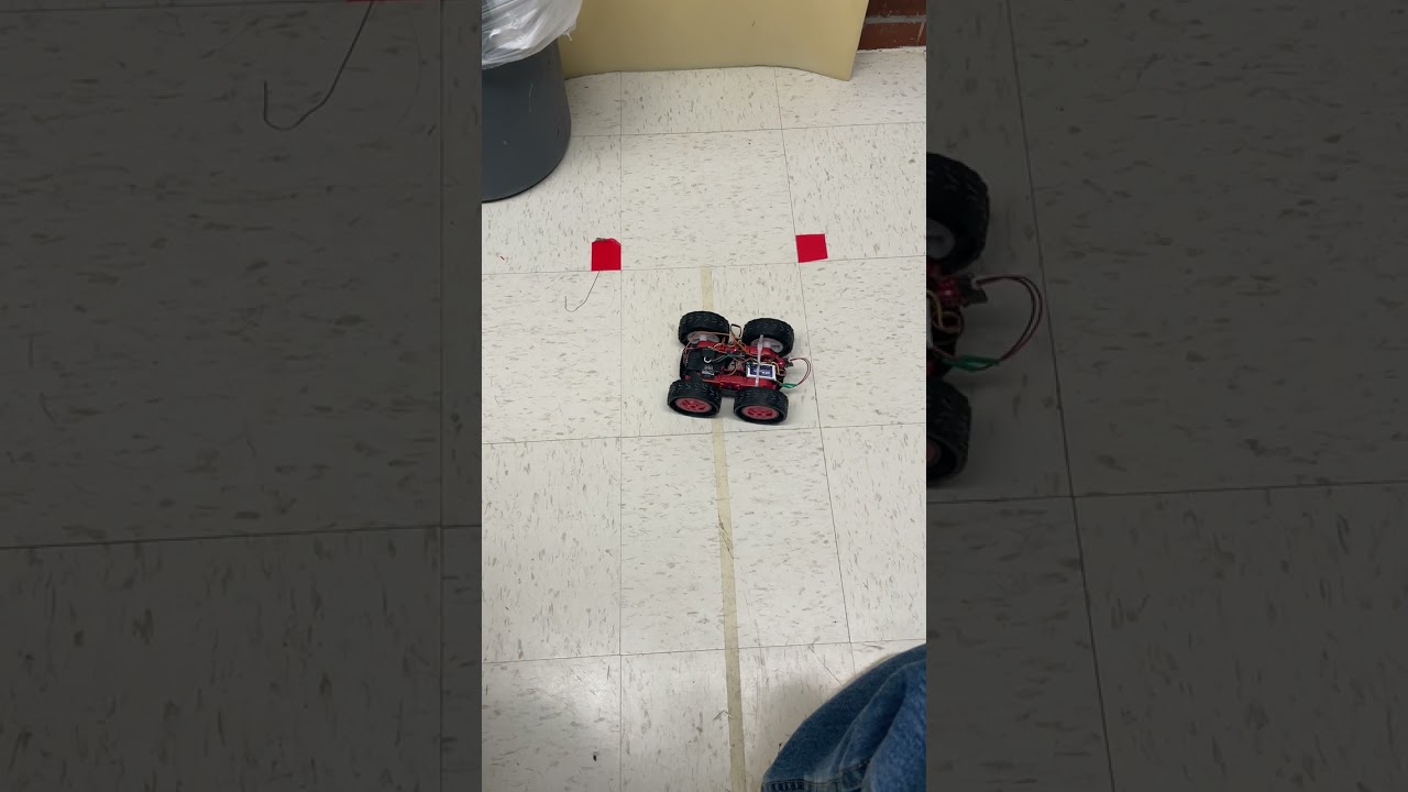
In this case, the performance is good enough but still not very stable.
PI-Controller
I started to implement PI-Controller because the integration term can accelerate the converge speed. Similarly, for discrete cases, the integration term can be implemented as $I = K_i \times ((\sum_{j=1}^{t-1}\text{YawError}^{(j)}) + \text{YawError}^{(t)} \times dt)$.
After tests, I found that when Kp=2, Ki=0.1, the general controller worked well.
Here, I set the clamp for the integration as 20. The readings’ plots are:
The yaw error vs time:

The P&I vs time: (Note Ignore the Derivative term here)

The video of the control:
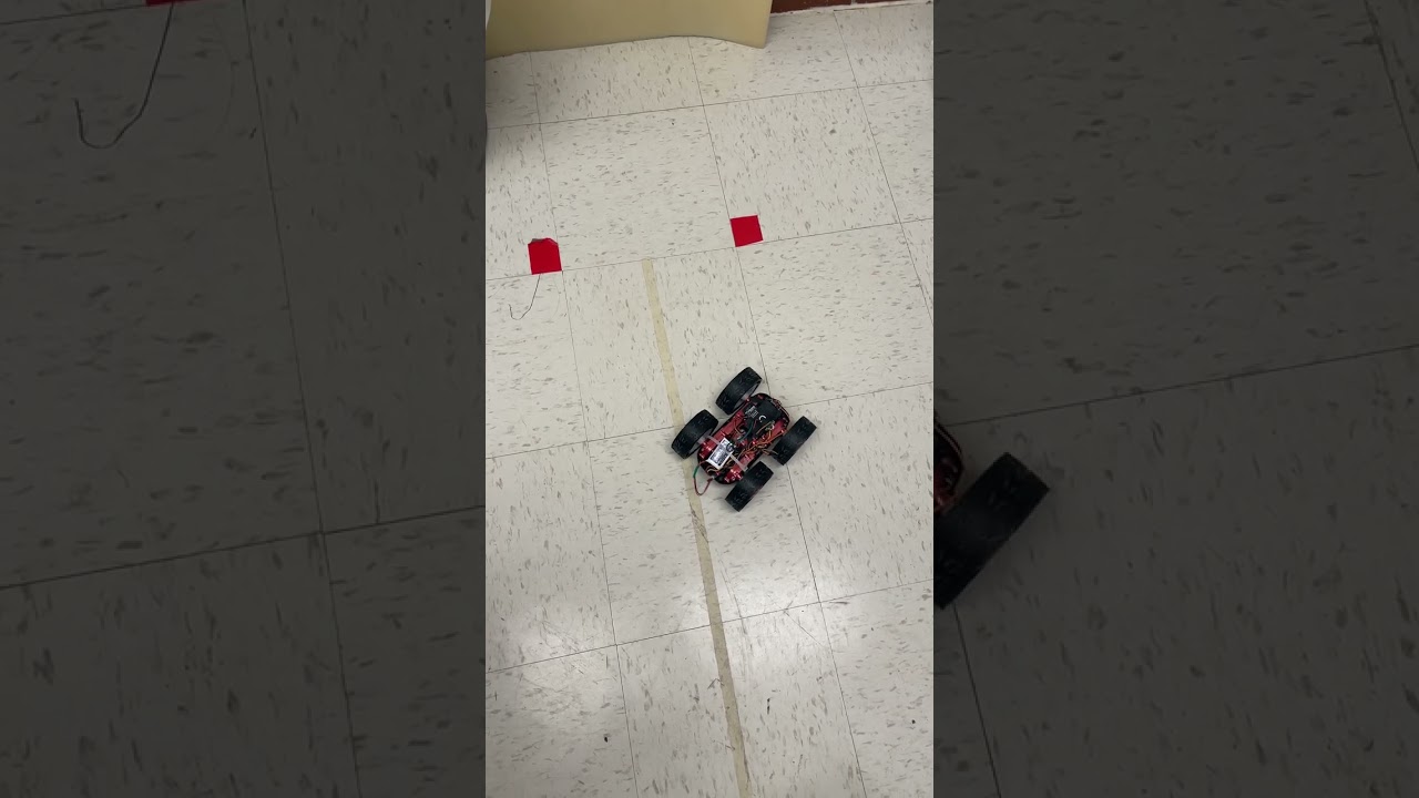
We can see that the overshoot is quite high. Consider to add the derivative control term.
PID-Controller
Bascially, D-controller can be implemented as: $D = K_d \times \frac{\text{YawError}^{(t)} - \text{YawError}^{(t-1)}}{dt}$
We get our orientation angle from IMU by integrating the angular velocity over time. Based on this, we are able to do the derivative of the yaw error:

After tests, I found that when kp=2, ki=0.07, the general performance was pretty good and stable.
The error vs time plot:

The PID values vs time:

I tested the car by kicking the car body to see whether it can recover its target orientation angle. The video is shown as:
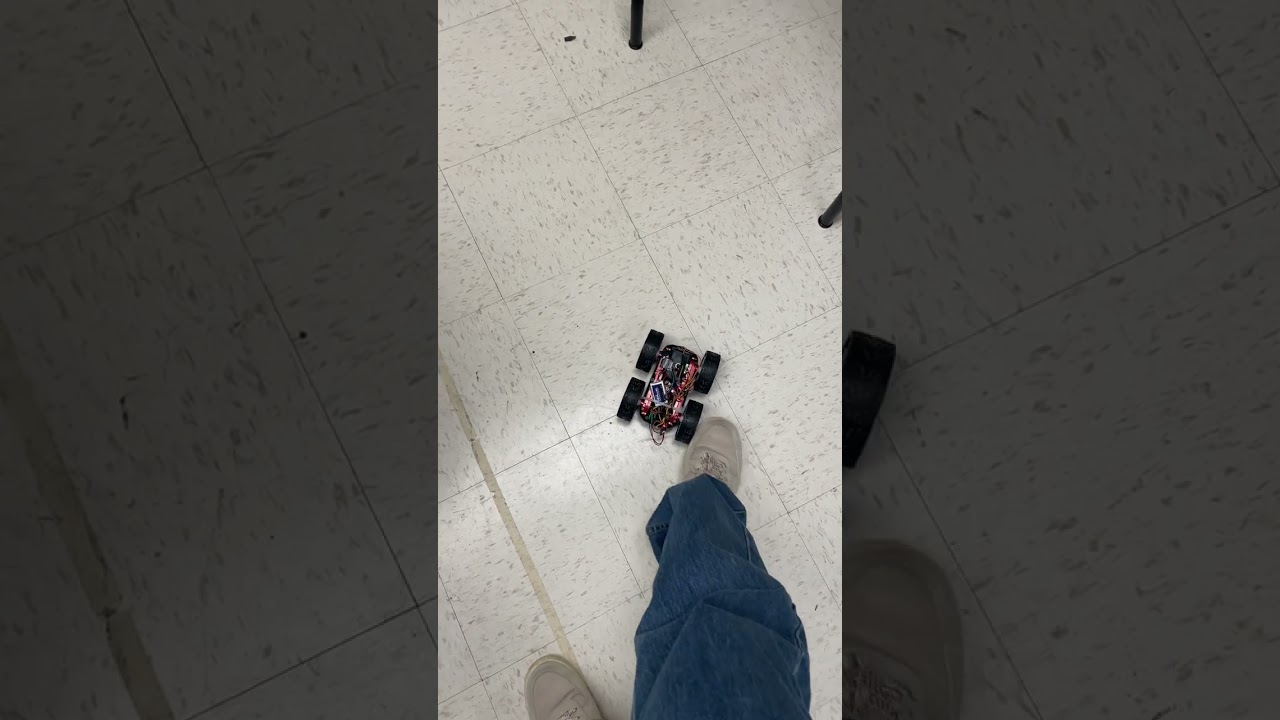
Generally, there is little noise for the derivative term, so the lowpass filter is optional.
Until now, the controller’s performance is quite great, and complete the orientation control task.