Vision and Learning for Robotics Manipulation and Grasping
This is a collection of “Vision and Learning for Robotics Manipulation and Grasping” projects for the course ELEC4260 (Intelligent Robots and Embodied AI) @ HKUST, 2025 Spring.
Project Overview
Trained and evaluated GraspCNN1 & GraspCNN2 and PoseCNN models for robotic arm manipulation, designing grasp synthesis strategies and validating the grasping pipeline in simulated and real-world settings.
- Detailed code implementation can be found in the Github code repo
This project covered robot–camera calibration, a basic grasping pipeline, pose-estimation-based grasp transfer, and data-driven grasp detection for different objects.
Task 1 - The Implementation of the Basic Pipeline
To enable collision-free movement and a stable grasp, the pre-grasp and post-grasp poses should be carefully calculated first, which shows as the following figure:
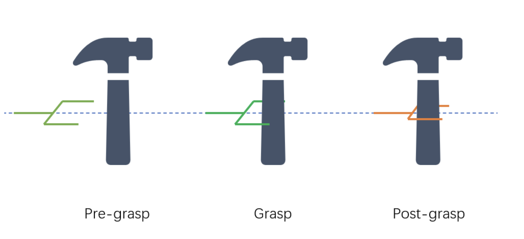
This pipeline leverages OpenCV’s Hough Circle Transform for detection and converts 2D grasps to 3D using camera intrinsics. Pre- and post-grasp poses are carefully calculated to ensure collision-free movement and stable manipulation.
The pipeline work in following steps:
- Detect a circle on the object
- Compute 2D grasp from the circle
- Convert 2D grasp into 3D grasp
- Computing the pre-grasp pose and post-grasp pose
- Controlling the robot to execute the grasp.
To better implement this pipeline (pre-grasp & post-grasp), the offsets should be adjusted using the orientation vectors obtained from the rotation matrix between the object and the camera/robot gripper.
The full video demonstration that the robotic arm grasps a Squash Ball, can be found below:
Task 2 - Object Pose Estimation & Functional Grasping
This task mainly includes implementations of the model PoseCNN, and the integration with the PoseCNN and the robotic arm grasping.
PoseCNN Model Implementation & Training
The model structure of the PoseCNN is shown as the following figure:
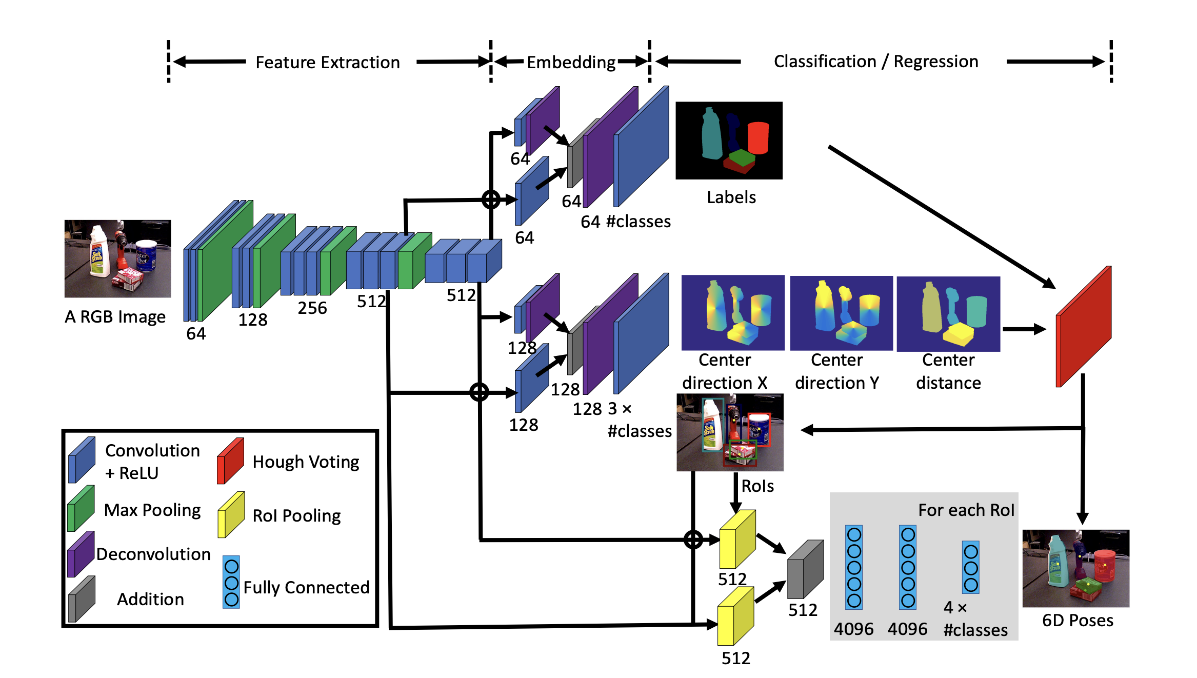
The workflow of this model structure includes a main backbone of CNN layers to extract major features in the input datasets. Then, the main branch is split into three branches which all share the same raw features from the main backbone layers. One for segmentation (for object class label), one for the 3D translation estimation (object localization), and one for the 3D rotation.
The model’s loss consists of the losses from all the three branches (with equal loss weights for training, which might cause trouble for whole-model optimization, especially when there is one object/class which is much more important in the context of the problem settings). Based on the provided hardware resources, the training batch_size is 4, the total training epoch is 4, Adam is the optimizer with provided learning_rate 0.001.
The model’s training progress is shown as the following figure:
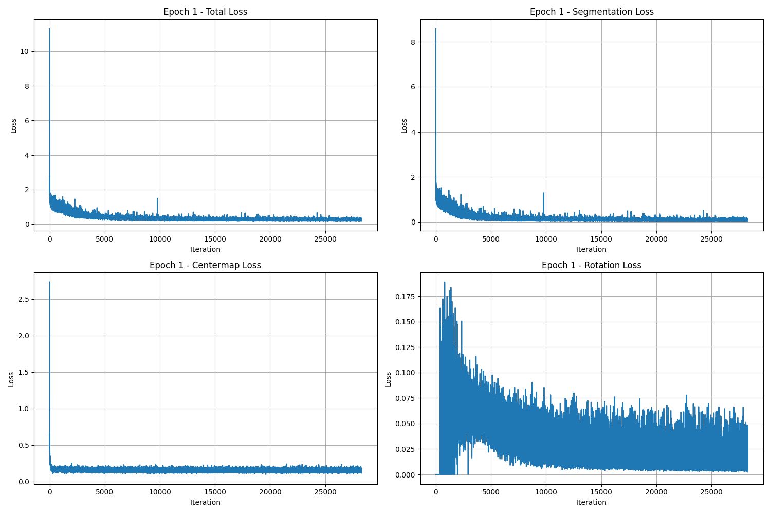
Due to the scale of the datasets and the model memory size, the losses only drastically drop during Epoch 1. There are no obvious optimization during the remaining epochs. Among the three classes, the performance of the translation estimation is the trickiest one, which causes the failure of the localization of the segmentation and therefore the rotation rectification. Even after the 4 epochs, the centermap loss is about 0.12, which shows great threats to the Task 2’s experiments.
The model’s validation results can be found below with the segmentation, translation, and rotation estimation visualization:
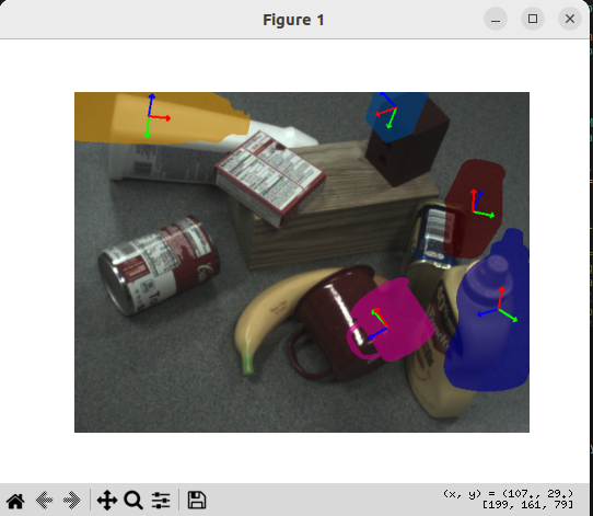
In this figure, we can easily find that the performances of the segmentation and the rotation are really good. However, the predicted areas cannot be located at the real objects’ locations, which is caused by the performance of the translation class (centermap). This is related to the intrinsic design of the model structure. This can be greatly mitigated by applying the ICP between the predicted areas and the real object’s areas.
Also, this might be addressed if we apply one hyperparameter for each of the class while model training. For example, we can first set the model total loss as:
\[\textit{total loss} = \lambda_1 L_\textit{segmentation} + \lambda_2 L_\textit{centermap} + \lambda_3 L_\textit{rotation}\]An alternative would be to tune the relative weights of the segmentation, centermap, and rotation losses. This approach was not evaluated in this project; ICP was used to refine the pose estimates instead.
Improving Pose Estimation with ICP
I implemented Iterative Closest Point (ICP) in two ways: a custom implementation with KD-tree nearest-neighbor search, and an implementation using o3d.pipelines.registration.registration_icp from Open3D. The resulting alignment was integrated into the robotic grasping pipeline.
Pipeline Deployment with the Robotic Arm
To make the process more straightforward and easier to debug, I applied another ICP before the raw comparison between the real object captured by the camera and the ground truth object. The refined results after two rounds of ICP and the predicted grasping motion can be found in the following demonstration video.
Task 3 - Data-driven Grasp Detection
I implemented GGCNN and GGCNN2 for data-driven grasp detection and integrated the grasping pipeline with the robotic arm.
GGCNN Model Implementation & Training
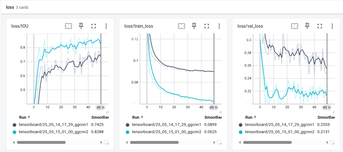
The model definition implementations are strictly following the original definitions on the corresponding papers. Both use CNN layers as the main structure and predict for different contexts - positions, orientations, and grasping width.
The model’s general training losses, validation losses, and the IOU (Intersection over Union) results can be found in the following figure:
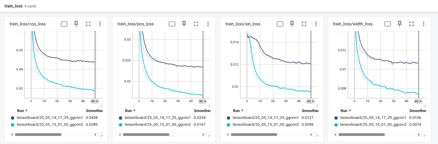
The training details of the position loss, orientation loss (sin, cos), and the grasping width loss can be found in the following figure:
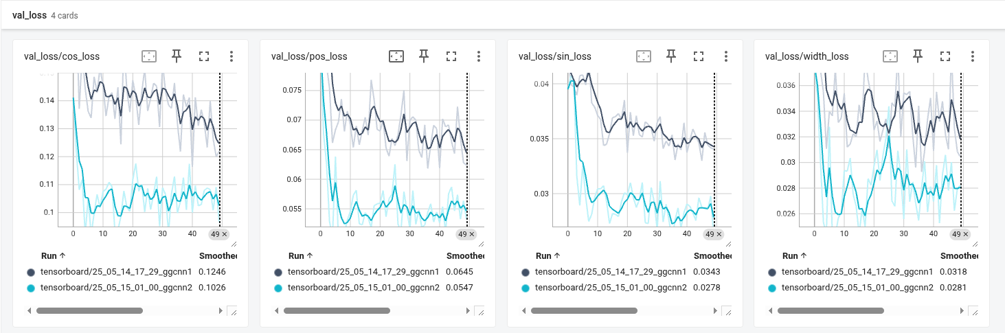
The validation results of the position loss, orientation loss (sin, cos), and the grasping width loss can be found in the following figure:
One of the evaluation results on the same real object (wooden spoon) of the GGCNN1 & GGCNN2 is shown as the following figures, with the classification (segmentation), predicted grasping position and orientation, and the grasping quality:
- GGCNN1:
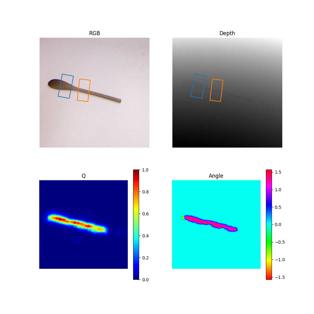
- GGCNN2:
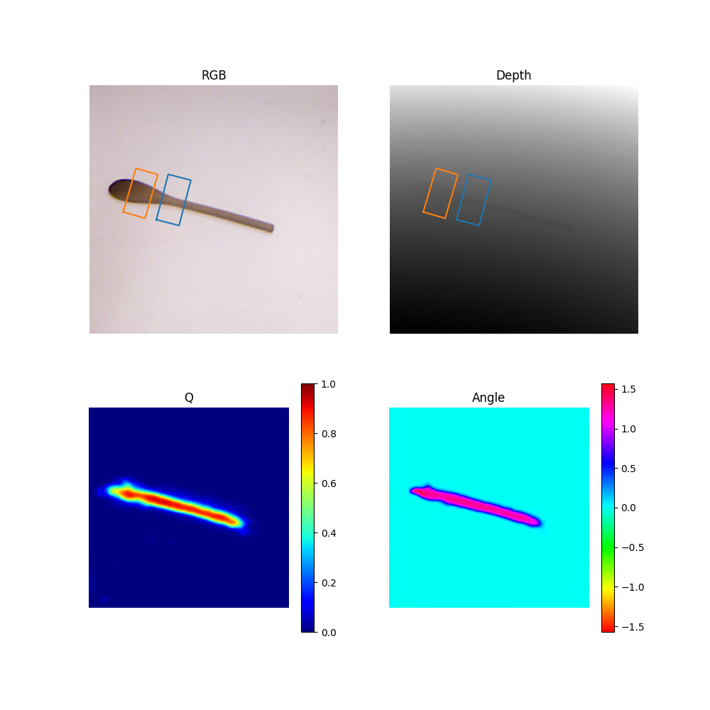
Based on the visualization results, we can see that the GGCNN2 has a better performance in the grasping position and orientation estimation, and therefore the grasping quality is also better.
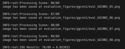
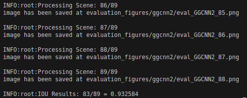
The IOU results of the GGCNN1 and GGCNN2 can be found in the following figure:
- GGCNN1: 76/89
- GGCNN2: 83/89
Integrating Grasp Detector in the Pipeline
I have integrated everything into the general pipeline. But due to the properties of the data-driven approach, the grasping performance is not very stable, and the success rates of each trial object are not very high.
The video demonstration of the integration can be found below:
In general, three objects are tested:
- Tripod (success rate 8/10): This success rate is quite high probably due to the similar shape to some of the trained objects’ shapes.
- Glue Stick (success rate 6/10): This rate is a little bit lower, because firstly the color of the stick is quite similar to the background mat, and secondly the object itself is smaller. So, this performance is quite acceptable.
- Screwdriver (success rate 9/10): This rate is quite hight because this object is much bigger, and the head of the driver is green which is highly different from the background color. Also, the light reflection on the driver from the ambient light is less due to its surface texture.